Geometric optics 👓
1. Light sources
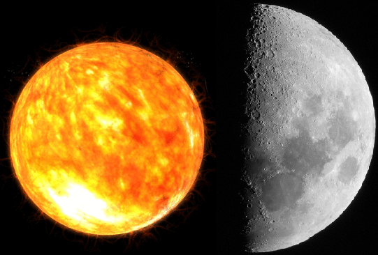
There is a between these two light sources.
- Light is produced by energy processes:
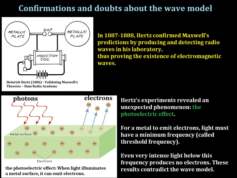
- the Sun → energy comes from the fusion of 4 Hydrogen nuclei to form a Helium nucleus
- fire → energy comes from heat
- lamp → energy comes from electricity
All objects that are illuminated and reflect light are secondary sources.
It is mainly through secondary sources that we see.
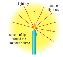
The flame of a candle or a distant star can be considered a point source,
because it is small compared to its distance from the observation point.
Point sources emit light in all directions as well.
2. The ray model of light
,
light travels in a straight line at a speed of 3 x10⁸ m/s (in air or vacuum),
we can therefore model it with rays.
This allows us to explain much of what we observe in everyday life.
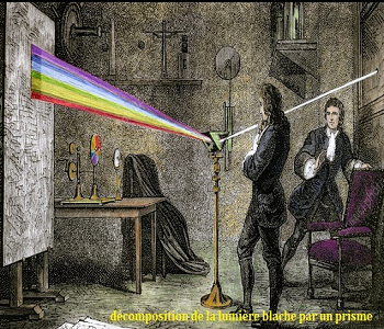
However, it does not explain phenomena like the rainbow 🌈.
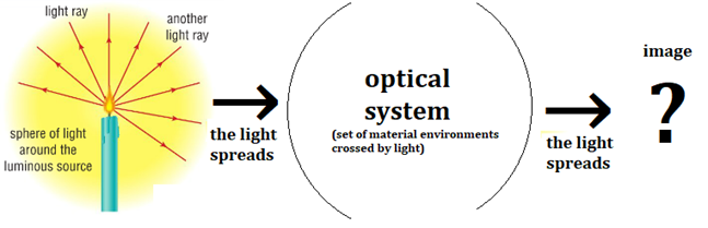
Something seems off in the image on the right,
In reality, we only see the illuminated area on the screen:
We don't directly see the light but what it illuminates.
So the light ray is just a mathematical abstraction,
hence the name geometrical optics!
3. Seeing objects?

It is quite surprising to see yourself in a mirror for the first time or that a straw appears to be broken when it is intact.
These two images illustrate a simple idea, which we tend to forget:
The eye does not have direct access to objects; it has access to the light received by the retina.
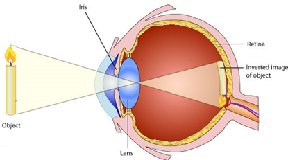
- The image (reversed by the lens) is formed on the retina.
- Nerve cells convert the light into electrical signals
- The electrical signals are sent to the brain via the optic nerve
- The brain will interpret the electrical signals to form the image.
4. The role of interpretation
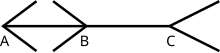
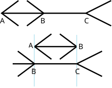
This is the Müller-Lyer illusion, which is explained by considering the brain's spatial perception.
The brain associates the > < arrows with objects moving away and the < > arrows with objects coming closer,
thus the perceived difference in length.
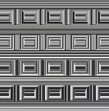
There are as many rectangles as circles!!
The circles are between the rectangles.
Normally, the brain chooses not to see them.
When analyzing the image, "it says":
This is a 3D image, so the circles don't exist, it's a perspective effect.

-
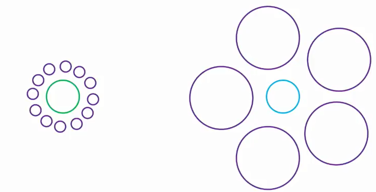
The circle on the left appears larger than the one on the right because:
- the left circle is surrounded by small circles
- the right circle is surrounded by large circles
- We judge the size of objects by contrast
- Even though we know the circles are the same size,
our perception is still influenced by the context

It shows a wall, with a cigar stuck in it, perpendicular to the wall.
Once we've seen the cigar, the illusion disappears,
the brain has changed its interpretation.
Kokichi Sugihara is a Japanese researcher and professor,
known for his work in visual illusions and spatial perception.
The arrow remains oriented to the right, it's magic!
This phenomenon relies on subtle manipulation of geometric properties
and the perception of two-dimensional vs. three-dimensional space.
The different parts of the arrow are such that our brain "smooths" the change,
giving us the illusion that the arrow remains oriented the same way, even after rotation.
In conclusion, we see with our eyes/brain,
it is an "active sensor" that interprets the information.
This illusion would not be possible if we looked directly at the object with our eyes,
because unlike a camera that forms a flat image, we are capable of seeing in 3D...
5. Seeing with two eyes
Since the angle is slightly different, the brain receives two slightly shifted images,
and it can use this shift to form a three-dimensional image.
When we close one eye, we notice a slight change: it's the transition from 3D to 2D.
At birth, a baby sees double. It takes about six months to see properly in 3D.
If I trace several rays from the flame to its image...
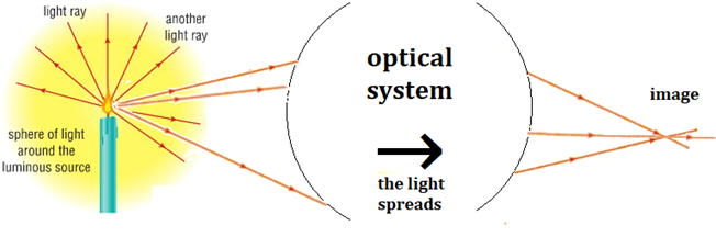
All the light rays coming from my source must intersect at the image point.
The image is the area in space where the rays from the object converge.
Okay for the image of a point source, but...
- We assume that the image can be:
- enlarged
- reduced
- inverted
- but not distorted!
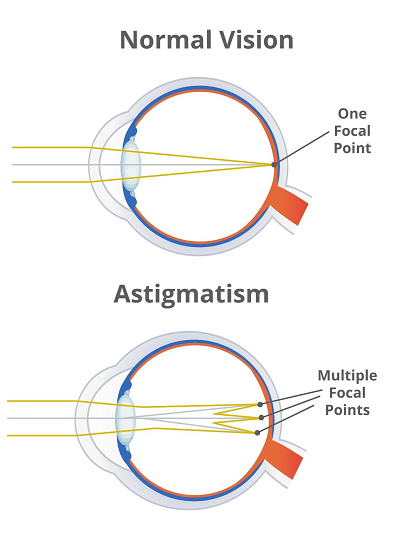
This is the case when the eye is astigmatic, meaning it has an irregular shape in its optical structures,
mainly in the cornea (or sometimes in the lens),
which causes light rays to be incorrectly focused in a single point on the retina.
Instead, the astigmatic eye produces a distorted image, often in the form of blurry spots or extended lines.
In the same way, optical systems are stigmatic or astigmatic.
-
We will work with stigmatic optical systems:
- all light rays from a point source intersect at a single point
- there is no image distortion.
The mirror is a stigmatic optical system.
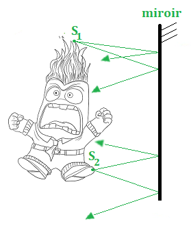
To represent the image of my figure in the mirror,
I look for the images of two sources, S1 and S2
The light rays diverge (they spread apart).
So, no chance they will intersect!
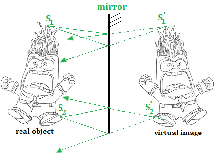
what matters are the light rays that reach the retina.
The rays from S1 appear to come from S'1
We can see S'1 with a sensor (camera, eye...) located at the object level,
but if we place a screen at S'1, we see nothing, because no ray reaches there.
This is a virtual image, we can see it, but it does not exist.
To find it graphically, we need to extend the reflected rays.
1. Law of Reflection
-
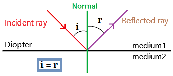
Vocabulary is important here:
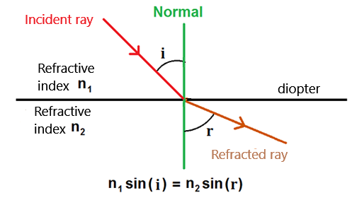
- The diopter: the surface separating two different media.
- The normal: the perpendicular to the diopter,
angles are measured relative to the normal. - The incident ray: the ray that "arrives" at the diopter.
- i: the angle of incidence.
- r: the angle of reflection.
According to the law of reflection: i = r
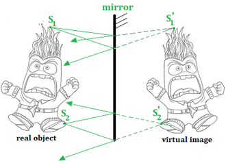
As we saw in Section III, the image of an object in a mirror is a virtual image.Geometrically, the mirror acts as an axis of symmetry between the object and its image.
Only a plane mirror is stigmatic; a spherical mirror is astigmatic (distorting mirrors).
2. Law of Refraction

Therefore, the parts under water and in the air reach the retina at different angles.
Light is bent when it changes medium,
this is the phenomenon of refraction.
-
The speed of light depends on the medium it travels through: c = c0/n
- c: speed of light in the given medium
- c0 = 3.00 × 10⁸, the speed of light in air or vacuum.
- n: refractive index of the transparent medium, for example:
- In air: nair = 1 → cair = c0/nair = 3.00 × 10⁸ m/s
- In water: nwater = 1.3 → cwater = c0/nwater = 3.00 × 10⁸/1.3 = 2.31 × 10⁸ m/s
- In glass: nglass = 1.5 → cglass = c0/nglass = 3.00 × 10⁸/1.5 = 2.00 × 10⁸ m/s
its path is the one that takes the least time.
Suppose the light (on the right) travels from A to B,
passing through air and then glass.
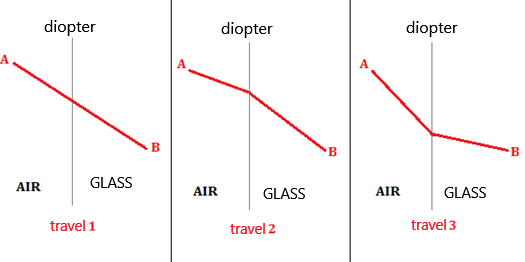
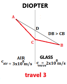
Given that the speed of light in glass is slower than in air (cglass = 2.00 × 10⁸ m/s and cair = 3.00 × 10⁸ m/s),
to minimize travel time, the distance traveled in glass must be reduced, and for this, the ray is bent!
Since the speed of light depends on the refractive index,
Fermat's principle implies a relationship between indices and angles: this is the law of refraction.
-
Law of refraction: n1sin(i) = n2sin(r)
- i: incident angle
- r: refracted angle
- n1: refractive index of medium 1
- n2: refractive index of medium 2
Rays are bent such that the distance traveled in medium 1 is reduced compared to the straight line.
Thus, the speed is lower in medium 1. Since c = c0/n (c and n are inversely proportional),
the refractive index n1 is higher, so n1 > n2.
The mathematician's response:
r > i → sin(r) > sin(i), because x → sin(x) is an increasing function.
Since n1sin(i) = n2sin(r) and sin(r) > sin(i), it follows that n1 > n2.
3. The Third Law of Snell-Descartes
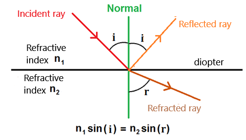
but part of the light energy is also reflected.
According to the third law of Snell-Descartes:
The reflected ray, the incident ray, the refracted ray, and the normal to the diopter lie in the same plane.
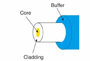
but there are also plastic fibers for specific applications.
Information is encoded as light signals (0: no light, 1: light) that propagate through the core.
But if the cladding is made of plastic or glass (thus transparent),
Vary the angle of incidence i from 0 to 90° by moving the small blue square to the left.
If i increases, at some point r = 90° while i < 90°; if we continue to increase i...
r > 90° is not possible: it is no longer refraction but reflection.
This is total internal reflection.
In this way, the light remains confined within the core of the fiber.
If i is greater than the critical (or limiting) angle °, reflection occurs.
- Help:
- If, for example, sin(i) = 0.5, to find the angle i,
we can use the arcsin function (the inverse of sin)
i.e., i = arcsin(sin(i)) = arcsin(0.5) = 30°.
According to Snell's Law: n1sin(i) = n2sin(r).
Since sin(r) = sin(90°) = 1, we get: n1sin(i) = n2.
- Thus: sin(i) = n2/n1
- i = arcsin(n2/n1)
To transmit information over long distances, losses must be minimized.
Unfortunately, with every reflection, a tiny portion of light intensity is lost.
Reducing the number of reflections is an easy solution.
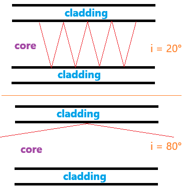
we notice that the larger and closer i is to 90°, the fewer reflections occur.
Thus, a high value of the angle of incidence i is required.
Total internal reflection results in far fewer losses compared to reflection on a flat mirror.
In practice, the indices n1 and n2 are close (typically: 1.46 and 1.48),
making the critical angle close to 80°, and therefore i > 80°.
1. Introduction: 2 Types of Lenses
They are widely used in various optical instruments such as glasses,
microscopes, and cameras. The crystalline lens of the eye is also a convergent lens.
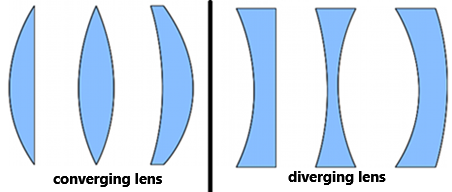
Two types of lenses are used:
-
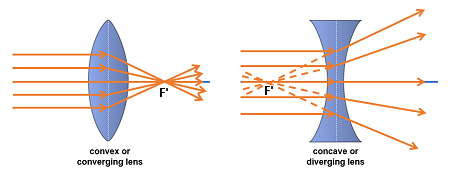
Convergent Lenses:
- Thicker at the center than at the edges.
- Converge parallel light rays towards a point called the focal point (F').
- Used to correct hyperopia, in magnifying glasses, etc.
- Thinner at the center than at the edges.
- Diverge parallel light rays, which appear to originate from a point called the focal point (F').
- Used to correct myopia.
2. Notations and Symbols
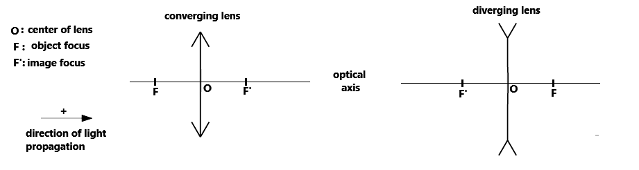
3. Three Rays to Trace the Image of an Object
- The incident ray passing through the center of the lens is not deviated.
- The incident ray passing through the object focal point F emerges parallel to the optical axis.
- The incident ray parallel to the optical axis converges towards the image focal point F'.
For divergent lenses, we use the ray that appears to pass through F or F'.
4. Constructing the Image of an Object Using a Lens
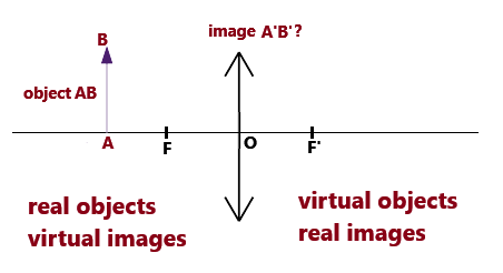
The goal is to find its image A'B' through graphical construction.
- We assume Gauss conditions,
meaning the rays are slightly inclined relative to the optical axis.
The optical system is then stigmatic. - A' is necessarily on the optical axis, so finding B' determines the image.
- On the left of the lens: objects are real, and images are virtual.
- On the right of the lens: objects are virtual, and images are real.
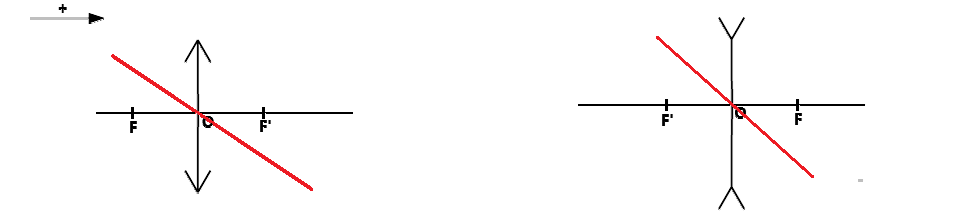
- Convergent Lens: Object is to the left of the object focal point
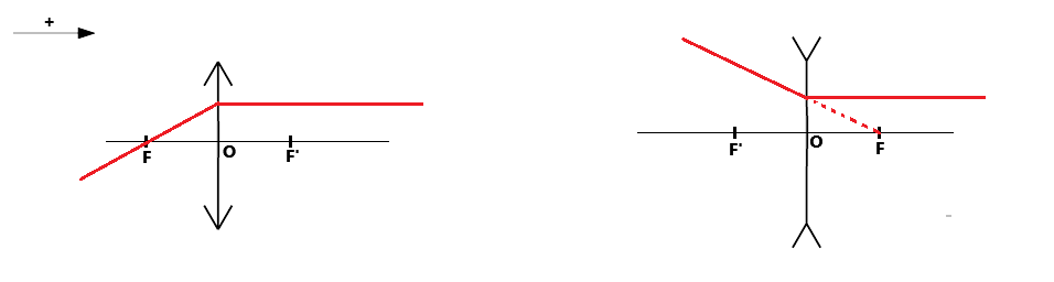
- Convergent Lens: Object is between the object focal point and the lens
- Divergent Lens: Object is to the left of the image focal point
- The ray that appears to pass through F emerges parallel.
- The ray parallel to the optical axis is deflected and appears to pass through F'.
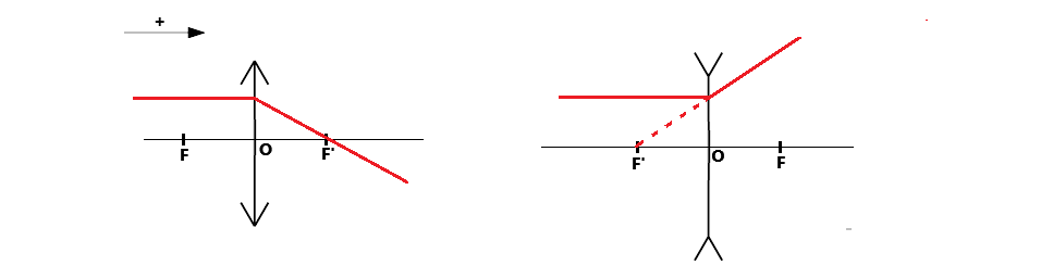
- Divergent Lens: Object is between F' and the lens
- The ray that appears to pass through F emerges parallel.
- The ray parallel to the optical axis is deflected and appears to pass through F'.
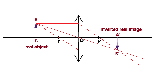
The resulting image is real and inverted.
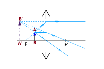
To find the image of B, extend the light rays,
as to an observer, the light rays appear to converge to the left of F.
The resulting image is virtual and upright.
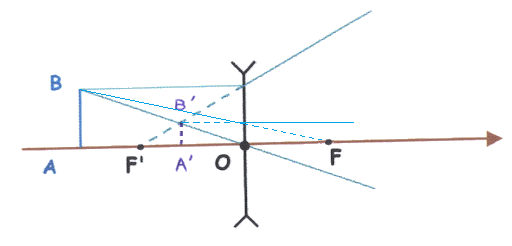
The image is upright and virtual.
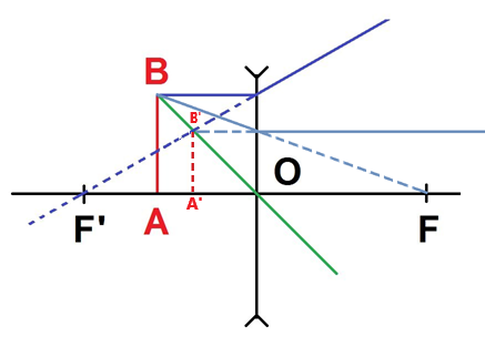
The image is upright and virtual.
5. What if the Object is at Infinity...
a building a few dozen meters away is distant enough to be considered "at infinity."
How to represent the light rays from such objects?
The source moves closer to and farther from the sensor, and the angle represents the maximum deviation between rays arriving at the sensor.
If the angle is 0, it means the rays are parallel to each other; here, the animation stops at 0.8°.
It is observed that rays from an object at infinity are parallel.
Or not... 😱, the scientific mindset also considers context in experiments or simulations.
Here, a point source on the optical axis is considered—a specific case, but what if the source is offset?
Light rays from a source at infinity remain parallel to each other.
This aligns with the mathematical assertion that parallel lines meet at infinity.
Interestingly, the rays are no longer parallel to the optical axis.
Rays from each source arrive at the sensor at a different angle.
This difference is called the apparent diameter, which depends on the size and distance of the luminous object from the sensor.
The Sun has a very small apparent diameter (0.5°) because it is very far away.
To summarize, if looking for the image of a point source at infinity, there are two cases:
- The source rays are parallel to the optical axis
- The source rays are not parallel to the optical axis
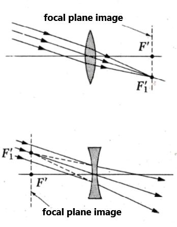
This point is called a secondary focus.
It lies in the plane perpendicular to the optical axis and containing F'.
This is called the image focal plane.
Of course, there is an equivalent on the side of the object focal point.