
Electricity 💡
1. Electric Voltage
Electric voltage represents the force that drives electrons to move through an electrical circuit; it is the "driving force" for electrons.
This force comes from a charge imbalance between two points in a circuit, called the potential difference (or pd).
The unit for measuring the value of an electric voltage is the Volt, symbolized by (V).
For voltages, we often use the symbol U; for example, if the voltage is 5 Volts → U = 5V.
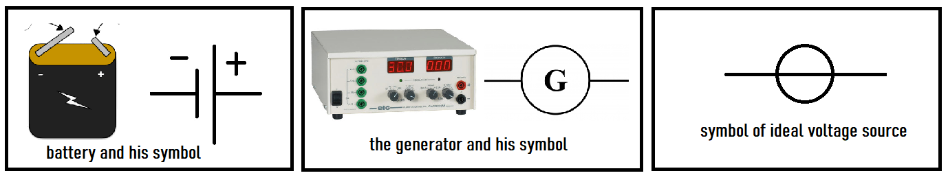
To obtain an electric voltage in a circuit, a generator is required:
Notes:
- The ideal voltage generator is used with a series resistor to model a generator (to be specified later!).
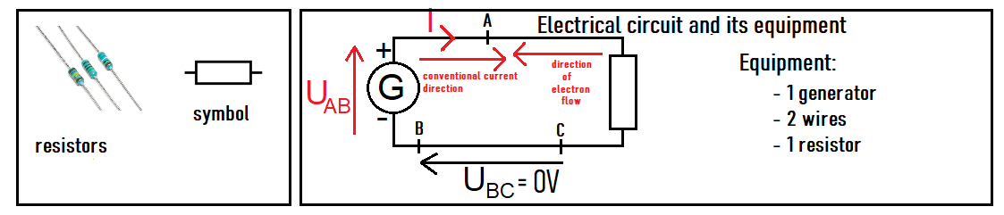
- In an electrical circuit diagram, "a line" represents a component in itself:

2. Electric Current Intensity
Intensity is concretely proportional to the number of electrons passing through the electrical wire per second.
It is denoted by I, and the unit of measurement is the Ampere (A); for example, if the intensity is 0.5 Amperes → I = 0.5A.
3. Study Context: Direct Current
We speak of direct current when the voltage supplied by the generator does not change over time.
This is the best way to approach this part of physics, even though it's not the most common regime! (haha, hum...)
For example, EDF supplies a voltage that alternates between 230V and -230V (effective values).
The knowledge acquired in the study of direct current is essential for the study of other regimes.
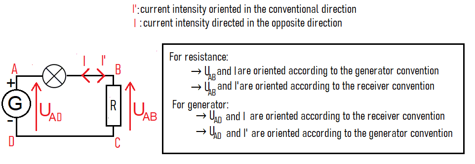
4. Directions and Conventions:
Using a generator, we can make electric current flow through a resistor (or ohmic conductor):
- The value of a resistor is called resistance, denoted by R, and the unit is Ohm (Ω); for example, R = 100Ω.
- Common misuses (often used by myself too 😱):
- "intensity" instead of "electric current intensity"
- "resistance" instead of "resistor"; we say "a resistance of 100Ω" instead of "a resistor with resistance of 100Ω"
- The conventional direction of current is from the positive terminal to the negative terminal (like I on the diagram).
- Electrons flow in the opposite direction, from the negative terminal to the positive terminal (because they are negatively charged, so attracted to the positive terminal (opposite charges attract)).
- UBC = 0V because in a wire there is no potential difference: each point is in the same electrical state.
- When we talk about an electrical circuit, voltage is always measured between two points of a circuit.
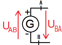
- Thus, the notation U is incomplete! Between points A and B, the voltage is written as UAB or UBA.
- To draw the arrow corresponding to UAB:
- the first letter (A) corresponds to the top of the arrow,
- and the second (B) to the bottom of the arrow.
- UAB = VA - VB, that is, the electric potential at A minus the electric potential at B.
- UAB and UBA are two opposite voltages, so UAB = -UBA.
5. Series or Parallel?
Vocabulary note: all devices with two terminals are called dipoles.
There are two types of connections:
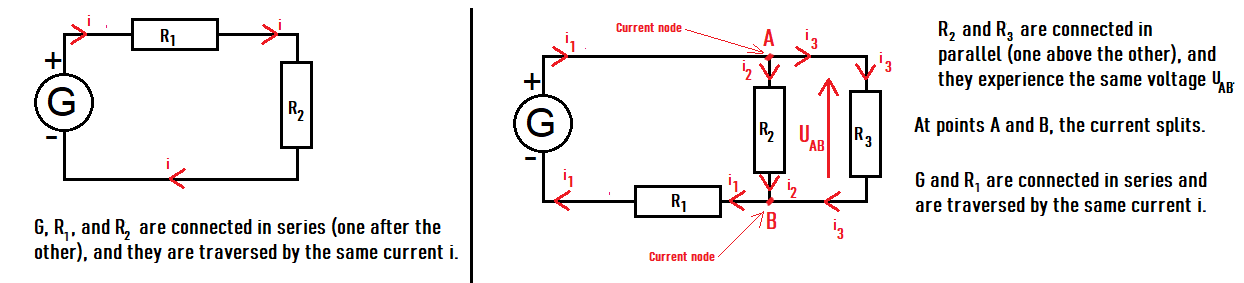
- In series, the dipoles are connected one after the other and are traversed by the same current.
- In parallel, the dipoles are connected one over the other and undergo the same voltage.
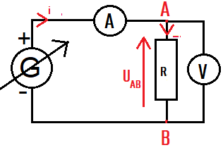
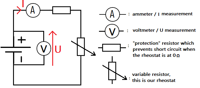
6. Ammeter and Voltmeter
As shown in the diagram below:
- An ammeter is connected in series
- A voltmeter is connected in parallel
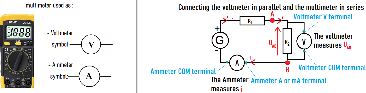
Note: measuring devices are considered not to change the operation of the electrical circuit.
7. Other Symbols
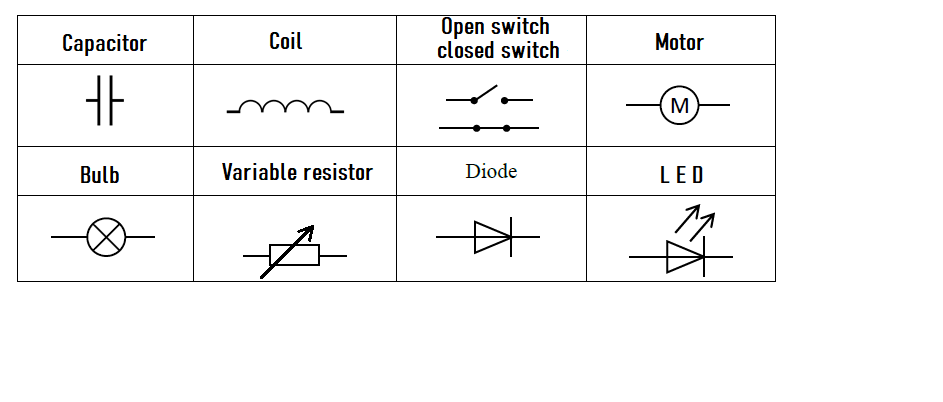
Match the pairs
symbol-image
Ohm's Law - Resistance Characteristic - Part 1: Setup and Measurements
1. Using the + and - buttons, vary the voltage.
2. When the value is satisfactory, press Measure
3. Once you have obtained all 7 values:
Voltmeter
Voltage (U) : 0 V
Ammeter
Current (I) : 0 mA
Measurements:
| Measurement 1 | Measurement 2 | Measurement 3 | Measurement 4 | Measurement 5 | Measurement 6 | Measurement 7 | |
|---|---|---|---|---|---|---|---|
| U (V) | - | - | - | - | - | - | - |
| I (mA) | - | - | - | - | - | - | - |
You have taken 0 / 7 measurements.
You have completed the measurements, click on "I'm done"
to plot the characteristic of the resistor.
Ohm's Law - Plotting the Characteristic - Determining the Resistance Value
Ohm's Law: U = RI
- U (V)
- I (A)
- R (Ω)
1. Why the characteristic of a generator?
In part 1, I gave 2 symbols to represent 2 different generators:
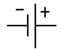 : this is the symbol that represents an ordinary battery.
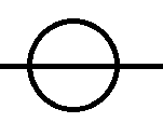 : this is the symbol of an ideal voltage generator.
An ideal voltage generator is a generator that is capable of always delivering the same voltage under all circumstances, which basically means it doesn't exist!
But ... what’s the difference between a battery and the ideal generator?
This is exactly what we are going to discover in this section! We will proceed step by step:
- Set up the circuit to measure the voltage U across the battery terminals and the current I in the circuit (we need to be able to vary U and I).
- Take 7 measurements of U and I to plot the characteristic (the curve U = f(I) which represents the voltage as a function of the current).
- From the 7 points, plot the characteristic.
- From this characteristic, find a realistic model of the battery and formulate an equation.
2. Equipment
For the setup, we will need the following equipment:
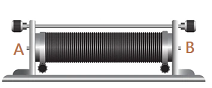
- A 9V battery, a 20 Ω protection resistor, wires, and ... a 200 Ω rheostat.
A rheostat looks like this: 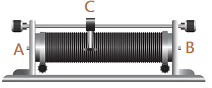 , you can move the slider by hand (the C part).
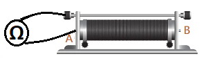
I connect an ohmmeter between A and C to get the resistance value. What happens when we move the C slider?
The resistance value varies up to the maximum value of 200 Ω. If we connect between A and B, the resistance is also 200 Ω.
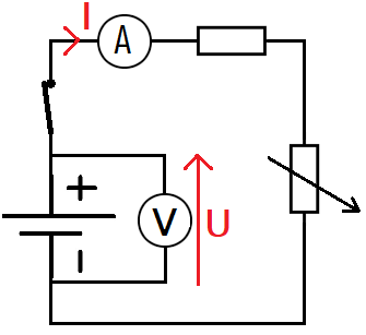
3. Circuit
Next, we will set up the following circuit:
If you’ve been following closely, here we won’t directly vary U or I but we will vary...
... we will vary the circuit resistance using the rheostat slider!
As a result, I and U will also vary, allowing us to measure 7 different values.
We will resume the setup from the introduction and adjust the resistance of the rheostat to get our measurement points.
I added an open switch, which is our first measurement point (important) U = 9V with I = 0 mA.
To get other measurements, you need to start by (otherwise, I will always be 0).

1. When the values of U and I are satisfactory, press Measure
Adjust the rheostat resistance using the slider to vary U and I.
2. Once you have obtained all 7 values:
Voltmeter
Voltage (U): 9 V
Ammeter
Current (I): 0 mA
Measurements:
| U (V) | Measurement 1 | Measurement 2 | Measurement 3 | Measurement 4 | Measurement 5 | Measurement 6 | Measurement 7 |
|---|---|---|---|---|---|---|---|
| U (V) | 9 | - | - | - | - | - | - |
| I (mA) | 0 | - | - | - | - | - | - |
You have completed 0 / 7 measurement(s).
You have finished the measurements, click on "I’m done"
to plot the generator's characteristic curve.
We found the voltage/current relation of the battery, which is U = 9 - I
The general formula for a generator is U = E - rI, in our experiment E = 9V and r = Ω.
- E is the electromotive force (emf) of the battery.
- Why electromotive force? Remember that the role of a generator is to move electrons → see (I)!
- We say that E is the voltage when the battery is not supplying any current. Indeed, U = E - rI, so if I = 0 then... U = E.
- E behaves like an ideal voltage generator, hence its symbol:
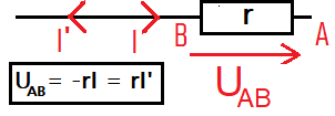
- If you followed part III closely, you know that -rI represents the voltage across a resistor of value r.
- And if you understood part IV, you know why it's -rI and not rI
- It's because the voltage and current are oriented in the same direction (we use a generator convention, whereas a resistor is a receiver).
- Ohm's law for the resistor r:
We have finally obtained the equivalent circuit of a battery, which can be generalized to other generators: Congratulations 🎉
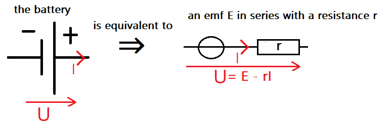
Do you remember the question from the beginning?
Well, the difference lies in the series resistance r, which reflects the "imperfect" nature of the battery.
Since from the 9V emf of the battery, we have to subtract the value of rI, so -rI represents a voltage drop compared to the ideal generator.
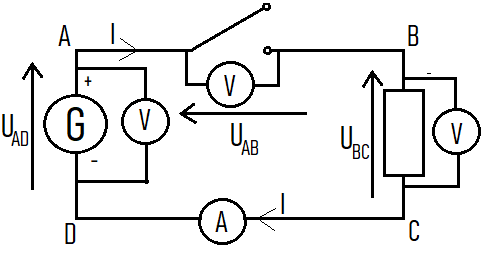
1. Can we have voltage without current?
We create the setup shown opposite.
List of equipment:
- 1 generator
- 1 ammeter
- 3 voltmeters
- 1 resistor
- 1 switch
- 10 wires
We set the generator dial to 6V.
Since the switch is open, we necessarily have I = 0A.
Is the generator's voltage UAD = 0V?
1. Can we have voltage without current?
, the voltmeter shows that the voltage UAD is close to 6V.
Even if there is no current, the generator still provides its voltage.
Remarks:
- UBC = RI = 0V because I = 0A
- Mesh law (seen later): UAD = UAB + UBC
- UAD = UAB + 0
- Therefore, UAB = 6V, the voltage across the open switch is around 6V.
- The reverse is false, there is no current without voltage.
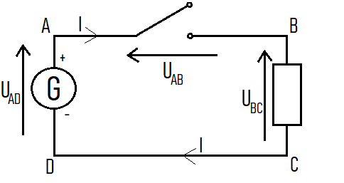
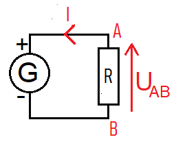
2. Receiver convention and generator convention
We have seen that Ohm's law is written as U = RI.
Can we write UAB = RI with the notations in the diagram opposite?
2. Receiver convention and generator convention
, the voltage UAB = -RI with the notations of the diagram.
I and UAB are oriented in the same direction on the diagram, this is the generator convention.
To have UAB = RI, we must use a receiver convention, meaning UAB and I are oriented in opposite directions.
Logically, we use the generator convention with generators and the receiver convention with receivers.
In the diagram opposite, the current I should be oriented in the other direction to have UAB = RI and I in the conventional current direction.
The formulas (such as UAB = RI) are written with respect to the electrical diagram, (so make sure to draw diagrams!)
3. A mesh, a node...
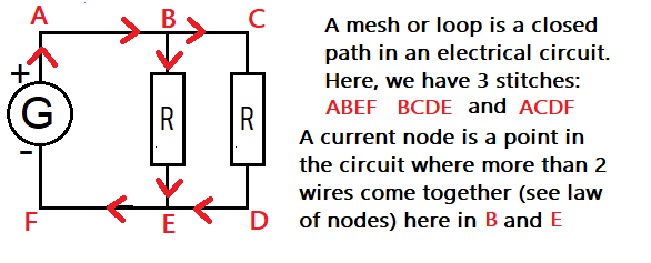
1. Understanding the Node Law
Currents I and I1 arrive at node A,
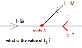
Simply by stating that since the current has reversed direction, it has the value: I2 = -7A, or by applying the node law!
- For node A:
- Incoming currents: I + I1 + I2
- Outgoing currents: none
- What flows in must flow out → Incoming currents = Outgoing currents → I + I1 + I2 = 0 → I2 = -(I + I1) = -7A
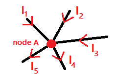
2. The Node Law ( Kirchhoff's Current Law )
If you understood what we did above, you need to make a diagram, since the law depends on the chosen current orientation:
- For node A:
- Incoming currents: I1 + I2 + I3
- Outgoing currents: I4 + I5
- Node law: I1 + I2 + I3 = I4 + I5
1. Statement of Kirchhoff's Voltage Law
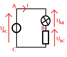
It is logical to think that the resistor and the lightbulb share the generator's voltage, so: UAC = UAB + UBC.
This is the law of voltage additivity or Kirchhoff's Voltage Law.
Kirchhoff's Voltage Law states that: The algebraic sum of the voltages in a loop is zero.
Here is the method:
- Choose a loop (only one is possible here!)
- Choose a positive direction to traverse the loop (see diagram)
- Mark all the voltages present in the loop
- Go around the loop adding all the voltages with a + sign if the voltage is in the same direction (UAC)
and with a - sign if the voltage is in the opposite direction (-UAB and -UBC) - This sum is equal to 0, which gives: UAC - UAB - UBC = 0, or UAC = UAB + UBC
2. An Example for Practice
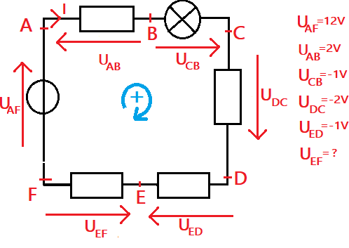
- According to Kirchhoff's Voltage Law: UAF - UAB + UCB + UDC + UED - UEF = 0
- So, UEF = UAF - UAB + UCB + UDC + UED
- UEF = 12 - 2 - 1 - 2 - 1 = 6V
- UEF = 6V